Dancing light
Description:

Notes.
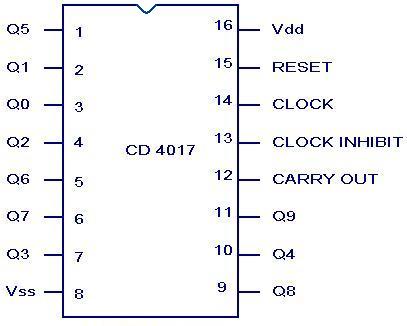
CD 4017 Pin configuration.
Description:
Here is a simple dancing light circuit based on NE555 (IC1) & CD4017 (IC2) . The IC1 is wired as an astable multivibrator to provide the clock pulses for the CD4017. For each clock pulse receiving at the clock input (pin14) of IC CD4017, the outputs Q0 to Q9 (refer pin diagram of CD 4017) becomes high one by one alternatively. The LEDs connected to these pins glow in the same fashion to give a dancing effect. The speed of the dancing LEDs depend on the frequency of the clock pulses generated by the IC1.
Notes.
- Assemble the circuit on a good quality PCB or common board.
- The ICs must be mounted on holders.
- The speed of the dancing LEDs can be adjusted by varying POT R2.
- The capacitor C1 must be rated 15V.
- Using different color LEDs could produce a better visual effect.
CD 4017 Pin configuration.
No comments:
Post a Comment